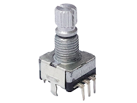
發表文章

240414 water pump

圖片
  【額定電壓】 DC 3.7V 【空載電流】 1.2A 【額定功率】 8W 【重量】 68 克 heater: about 2 Ohm, power with li-ion battery I think it's a mosfet only The blue line on left is said to be 2S 分壓線

Converting old USB step down power to variable voltage

圖片
I have few step down boards designed to provide 5V as USB ource, but I don't really use it these days. these boards having a bigger inductor than the cheap and small DCDC converter today These are small, and claim 2A, but if you use it to 1A continue, it would get hot pretty fast, on inductor, and the chip(the switching mosfet is in the chip.) The main chip on these old boards are MP2307 , data sheet claim to have 3A continuous. With these old board, the inductor is larger, should have better performance. Find the feedback resistor MP2703 use pin 5 as feedback pin, with a set of voltage divider, as R1 and R2 in the reference design. After few search, I found that the R2 (10K) is the R2 of reference design, which connect FB pin to ground. R6and R7 on my board is parallel connected as a R1 in reference design. Change the voltage divider resistors. In the data sheet, it shows how to calculate the out put voltage and some reference value.   I wish to use this board to power a plug form

arduino kitchen timer

圖片
This is what I want to use as a display under sun shine.  https://github.com/MakersFunDuck/Common-Kitchen-Timer-With-LCD-Replacement-Board I found this kind of display on Taobau, there are few common contact, just like the segment LED idsplay. This vender provide me some info:  奇耘电子 Even with frequent questions   1、 液晶屏有反射模式、半透模式,还有全透模式,不知道有什么区别,该如何选择?       反射模式:下偏光片不透明,所以不能接背光使用,适用于白天或者有外界光源的场合,优点是对比度高一些;       全透模式:透过率约40%左右,必须配合背光使用(否则会看到屏下面的元件或者PCB),优点是背光亮度高;       半透模式:介于反射和全透模式之间,透过率约30%,是否接背光都可以使用,比较灵活。   2、LCD段码屏有静态驱动和动态驱动的,请问如何区分?       静态驱动:只有一个公共端COM,每个像素都是单独电极引出。优点是和动态驱动相比显示效果好一些,缺点是引脚多;       动态驱动:超过2个以上公共端COM,每个电极至少控制2个以上的像素,需要时间分割扫描方式驱动。   3、LCD段码屏可以采用直流驱动吗?和LED数码管的驱动有什么不同?         LED数码管:直流驱动,由公共端接在阳极或者阴极,有共阳或者共阴的区别;      LCD液晶屏:交流驱动,公共端和驱动端都需要加交流方波信号,依靠改变两者的相位来控制对应的像素是否显示,这个是和LED数码管本质的区别,所以没有共阴或者共阳的说法。绝不能把公共端COM直接接地,通过控制驱动端接高电平来显示,这样子长时间工作容易损坏液晶屏。   4、LCD段码屏可以不用驱动芯片,直接单片机驱动吗?      静态驱动的段码屏,如果单片机的IO口数量够的话,可以直接驱动;动态驱动的屏,由于 需要时间分割的扫描方式驱动,而且偏压波形不好模拟,所以理论上是不能单片机直接驱动的。有些采用电

Soco TC RS485 decode

圖片
 I knew from web info that it's RS485 connection between units on TC, but the baud rate and format was not found on web. Base on the information I found at least BMS, motor controller, ECU and dash board are connected on 485. I have this 485 module on hand, decide to find out the traffic on 485. I first connect it to a FTDI, with DE/RD both tied to GND to receive data from bus. with ternimal on PC, I start to test on different baud rate, only at 4800 and 9600 I can receive "seems resonable" hex data. These are in 485, I tried to group them... 48 EB 01 20 F2 ED 6F 3F 3F 03 00 00 01 20 60 F2 3F 3F 48 3F E3 20 49 ED 6F 23 62 00 00 01 40 F2 3F 3F  48 EB 01 20 F2 ED 6F 3F 3F 03 00 00 01 20 60 F2 3F 3F 12 87 90 3F 3B ED 6F 23 62 00 00 01 40 F2 3F 3F  48 EB 01 20 F2 ED 6F 3F 3F 03 00 00 01 20 60 F2 3F 3F 48 3F E3 20 49 ED 6F 23 62 00 00 01 40 F2 3F 3F  48 EB 01 20 F2 ED 6F 3F 3F 03 00 00 01 20 60 F2  These are in 9600, also try to group it... C5 5C DA AA 02 00 00 02 0D B6 6B AA

Soco TC info

圖片
  source: https://www.mysupersoco.fr/forums/forum-general/questions-generales/sujet/tracking-complet-de-la-super-soco/ position of connector: tested guess on the pins of connector bus RS485 . à  4800 bauds the analysis: La plus petite période étant de 208 us,  la vitesse du bus est : 1/208*1000000 = 4808 , soit :  4800 bauds From another post of error code list: https://www.mysupersoco.fr/forums/forum-general/questions-generales/sujet/la-bible-des-codes-derreur-et-de-depannage-super-soco/ in error 94: communication fail on battery RS485 wire coded with color: Green-red=485+  Green-black=485- I guess it's a Mbus protocol, since there are BMS, motor controller, and soco's controller on the wires. info on the bus: https://wiki.voltgaraz.cz/index.php/RS-485 CPX BMS using 250kbps can bus message type:  https://wiki.voltgaraz.cz/index.php/CAN Controller side: https://www.mysupersoco.fr/forums/super-soco-tc-forum/general/sujet/travaux-sur-calculateur-configuration-remplacement/ 13TX /

Servo tester with watt meter(voltage and current) + display Part1

圖片
 function required:  Manual mode(VR or rotary encoder), Centering mode, sweep mode(low limit(800-1400ms)and high limit(1600-2200) settable, sweep speed adjustable) servo supplier voltage adjustable(5-7.2 or 8.4V?) or (by pass and lower to 5V) Current(5~8A should be good) and voltage monitor. Display. current position, voltage, current digital put put for chart plotting(Arduino IDE?) Option: servo signal Frequency setting 50Hz? First select the current sensor and voltage module. I have plenty on hand, basically divided into 2 category: analog current sensor(voltage to be calculated with voltage divider)   such as AS712, Max471, But you will need a MCU with good ADC, I plan to use esp32 for better display effect, but esp32 has bad ADC. Also if you switch between 5V and 3V MCU, the voltage divider need to be different. digital ones. Which has integrated good ADC and voltage divider, and usually has power meter function. and can be powered with 3.3 or 5V. The down side is that digital one

OPenLRS configurator not supported by chrome

From 2022, chrome killed all app on chrome, then this old but good system lost ways of configurate. here is a stand alone version on win32(works at 64 as well)  https://github.com/raul-ortega/openLRSng-configurator/releases/tag/3.8.8 I found this from a search : https://github.com/openLRSng/openLRSng-configurator/issues/35