Measuring current and voltage using 3DR power module and arduino
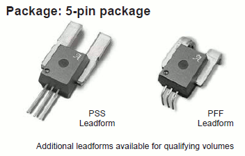
I used to use Allegro ASC current sensor like this one.


since it's calibration free, and out put voltage according to voltage. But these sensors are not easy to get in taiwan, and quite expensive.
As APM is popular, the 3dr power module comes with different source, good price, with 5V supply on it. this one should be handly.
while saying it's open source, I'm not quite sure where to get the code today. But a good source from sparkfun comes out form googling.
it's a attopilot voltage and acurrent sensor breakout, there are 90A and 180A versions.
Both are constructed with a shun resistor and a TI INA-169, which will out put a current based on the voltage difference on both side of shun resistor. Crossing this current through a resistor which connect to ground, then we have a voltage on this resistor, which is in function with the current.
As to voltage, there is a set of dividing voltage.
The good thing is that the product pages comes with datasheet, and example code, from the data sheet you can have good idea about the design and some major values on resistors.
For my 90A 3DR power module, it's easy to see the shun resistor(B in above chart) is 0.5mOhm

the questions remain on the dividing resistor on V sensing and the ground resistor for I sense, which is 73.2K on above chart.
the dividing resistor on v sensing could be vary from version to version, since there are some version for 3.3V ADC. As noted on the data sheet of atto.
New! Three Ideals ranges for small robotics applications:
o New 50 V / 180 Amps
o 50 V / 90 Amps1
o New 13.6 V / 45 Amps
• Low zero current offset and high sensitivity
• Analog output scaled for 3.3V ADC
• Self powered
• Compact thin design (4 x 15 x 19mm)
• Analog Voltage Outputs for Sensed Parameters:
o 50V/180A = 63.69mV / Volt 18.30mV / Amp
o 50V/90A = 63.69mV / Volt 36.60mV / Amp
o 13.6V/45A = 242.3mV / Volt 73.20mV / Amp
In mission planner, there are 2 parameters used to adjust the voltage and current measured:
Voltage Multiplier (BATT_VOLT_MULT)
Used to convert the voltage of the voltage sensing pin (BATT_VOLT_PIN) to the actual battery’s voltage (pin_voltage * VOLT_MULT). For the 3DR Power brick on APM2 or Pixhawk, this should be set to 10.1. For the Pixhawk with the 3DR 4in1 ESC this should be 12.02. For the PX4 using the PX4IO power supply this should be set to 1.
This is a parameter to adjust to match the real Voltage value with the displayed mission planner value.
Amps per volt (BATT_AMP_PERVOLT)
Number of amps that a 1V reading on the current sensor corresponds to. On the APM2 or Pixhawk using the 3DR Power brick this should be set to 17. For the Pixhawk with the 3DR 4in1 ESC this should be 17. Units: A/V.
This is a parameter to adjust to match the real Voltage value with the displayed mission planner value.
If we looking into the code provided by atto, it's basically the same concept.
So, no matter what is the value of resistors on the power module I got, I only need to determinate the ratio factor, since it's all linear.


留言
張貼留言