Adding hall sensor on RC sensorless BLDC motor
From a ebike forum:
This one adding hall sensors to outrunner Turnigy C8085-170 from out side.https://endless-sphere.com/forums/viewtopic.php?f=30&t=15686
But for big motors, put sensor inside is better.
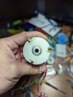
placing hall sensors between slots:
calculation
http://mitrocketscience.blogspot.com/2011/08/hall-effect-sensor-placement-for.html
Legend:
- edeg : electrical degrees
- erot: electrical rotation. 1 erot = 360 edeg
- mdeg : mechanical degrees
- mrot: mechanical rotation. 1 mrot = 360 mdeg
- pp : number of magnet pole pairs . 1 pp = 2 magnets (1 north, 1 south)
- s : number of slots (in the stator)
Equation 1: (360 mdeg / pp) = n mdeg per erot =n mdeg per 360 edeg
a motor controller that requires 120 edeg hall effect sensor placement. You need to find the number of mdeg per 120 edeg. So you just divide the above equation by 3.
equation 2: (360 mdeg / 3*pp) = m mdeg per 120 edeg.
For example, my Thunder tiger Heli motor, has 10 mags=5 pole pairs, and 12 slots on stator.
I could use the spacing is 24 degree

But, I think I will start with 120 mdegree placement.

But after a test, I found out that this mounting does not have enough flux

I have tested it with a VESC, with 44E sensors. I have had connector issue, it took my one day to figure out what's wrong.
I also tested with a inrunner one:
 |
| The facing of hall sensor has to be like this, to have enough flux. |

There are also singal pull high to deal with, in a RC sensored BLDC, the sensors are already pull high internally to 5V,(not sure if the ESC does pull high).
On my VESC(FSESC4.12 from flipsky), the pin on VESC are pull highed at 3.3V.
It still work if you connect a RC sensored BLDC to VESC.
But for a RC sensored ESC, not sure about the sensor table used.
it could be like this: https://www.rcgroups.com/forums/showthread.php?1556916-DIY-Brushless-DC-hall-confusion

and aline with bEMF:


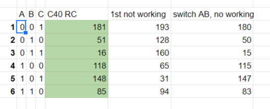
this chart explains when you read sensor 101, then A wire should be high, B wire should be low to drive to next step.
I use VESC's function to match my DIY hall sensored RC BLDC to existing RC sensored BLDC.for example:
This is a RC sensored BLDC tested in VESC tool under FOC mode, the hall sensor table shows rotor position with 3 hall sensors positions.001,010,011...etc.(the sequence is hall3 at highest bit, hall1 at lowest bit)

With my DIY hall sensor on a in runner BLDC, I manipulate the orders of hall1~3, and the position of hall sensors, to get similar angles and sequence.


I have tested a RC 13.5T sensored BLDC with VESC:


Connector could also be a issue: VESC using JST-PH 2.0mm pitch, the RC BLDC use JST-ZH 1.5mm as pitch


留言
張貼留言