VESC hall sensor table and use it to add hall sensors to RC sensorless motor, then nake it work with RC sensored ESC


The HALL sensors provide an indication as to where in the electrical revolution the rotor is. You get enough information to run the motor in BLDC mode depending on the HALL signal values. In BLDC mode there are six phases and the hall sensors conspire to make exactly six combinations.  


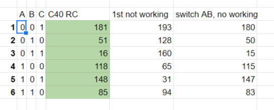
When driving the motor in FOC mode, the position of the rotor during an electrical revolution is thought of as a position on a compass: say 0-360 degrees. Now the three hall signals combine to make a 3-bit number 0-7. So now for each possible combination you note the average compass value when that value is output by the hall sensors. So if during 0-60 the combination 001 or "1" shows on the hall sensors, you put the average "30" in the table at position 1. Now 60-120 teh hall sensors show 011, so you put the average 90 in position 3 in the table. 


Now Benjamin decided to save a few bits by instead of counting the revolution in human-convention-units of a degree (i.e. 0-360), he decided to use units of 1.8 degrees. So now that first table-entry does not show "30 degrees" but "17 units-of-1.8 degrees". Except for a bit of rounding this is exactly the same. Close enough for our purpose. 

In VESC the e degree is total 200 instead of 360.

Now, there are several things that make this table more regular than random. For example, when you move the rotor half an electrical revolution, all the hall signals will change value. The value will be the ones-complement of what it was before. In three bits the ones complement of x  is "7-x". And an electrical revolution is 200(360 degrees), so half a revolution is 100. So table entries 1-6 should differ by 100. Is this difference not precisely 100, that points towards manufacturing tolerances in your motor. But in general it will be pretty close. 


I connected a RC sensored BLDC, which works with a RC sensored ESC
connect power wires and sensor wires according to ABC/UVW on VESC, I'm not sure about the wire sequence on VESC, I just mark it as I wish.

the run the hall sensor detection, I got a colon: 181,51,16,118,148,85
my guess is that if I manipulate the sequence of hall sensor wire, I should be able to make a similar table(value and sequence) 


Adding Hall sensor

calculation on the angle:

In short,120/nr of pole pairs~
Ex: 10 poles=5 pole pairs,
10poles 120/5=24 degrees
12poles 120/6=20 Degrees
14,poles 120/7=17.14 Degrees

my testing BLDC is a 14 poles one, I use 3D printer to do the hall sensor mount, to make it as close as possible to 17.14 degree, but, in fact, a RC sensored ESC does not care that much, slight different should work as well.


Few notes on sensor

1. there are analog hall sensor and digital hall sensor, most RC sensored BLDC use digital one, such as 3144E
2. Hall sensor need to be pull high. VESC does not pull high on ESC, so when testing you need a pull high resistor. My RC sensored ESC does have pull high resistor on ESC. But I made the pull high resistors on motor side, it works ok for both ESC.
3. facing: the flux has to be vertical to sensor face, otherwise it won't work correctly.

4. ready made sensored BLDC has hall sensor in the stator(or between), but mine motor does not have enough space to fit sensor,


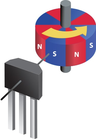
But you can the escape flux out of motor is enough to trigger hall sensor, you can also fit hall sensors on the outside of motor.
https://opensourceebikefirmware.bitbucket.io/development/Motor_control--Self-Learn_Hall_Sensor_Calibration_Mode.html

I made mine like this, the sensor position is adjustable to get my angle value close to my measurement of RC sensored BLDC


If the sequence is not correct, I simple switch the sensor wire.

But the RC BLDC I have does not comes with reverse function, so I have to first connect the motor to the RC ESC without hall sensor wires, to make sure the rotation direction of motor fit my need. 
The mark the power wire A,B,C corresponding to RC ESC.
I'm using a 4.12 VESC, the motor wire order is as following: 123 are ABC

source:https://shop.holybro.com/vesc-412_p1238.html


The hall sensor connector wiring of VESC is :
negtive-sensor3-sensor2-sensor1-temp-positive
black-    green-  yellow-   blue-    white- red (for most sensored motor color coding)

Then, connect motor to VESC with marked A,B,C, then do the hall sensor table detection thing.


留言

這個網誌中的熱門文章

Heltec ESP32+OLED+Lora, hardware testing

micro SD card for ESP32, on lolin32 with OLED and heltec 32 lora oled

Install Network Time Protocol(NTP) on BeagleBone with Angstrom linux and set local time zone