Servo tester with watt meter(voltage and current) + display Part1
function required:
- Manual mode(VR or rotary encoder), Centering mode, sweep mode(low limit(800-1400ms)and high limit(1600-2200) settable, sweep speed adjustable)
- servo supplier voltage adjustable(5-7.2 or 8.4V?) or (by pass and lower to 5V)
- Current(5~8A should be good) and voltage monitor.
- Display. current position, voltage, current
- digital put put for chart plotting(Arduino IDE?)
- Option: servo signal Frequency setting 50Hz?
First select the current sensor and voltage module.
I have plenty on hand, basically divided into 2 category:
- analog current sensor(voltage to be calculated with voltage divider) such as AS712, Max471, But you will need a MCU with good ADC, I plan to use esp32 for better display effect, but esp32 has bad ADC. Also if you switch between 5V and 3V MCU, the voltage divider need to be different.
- digital ones. Which has integrated good ADC and voltage divider, and usually has power meter function. and can be powered with 3.3 or 5V.
The down side is that digital ones use shunt resistor, so Watt and accuracy should be taken care. Be careful also the chip voltage limit, since some of them take voltage from power bus.
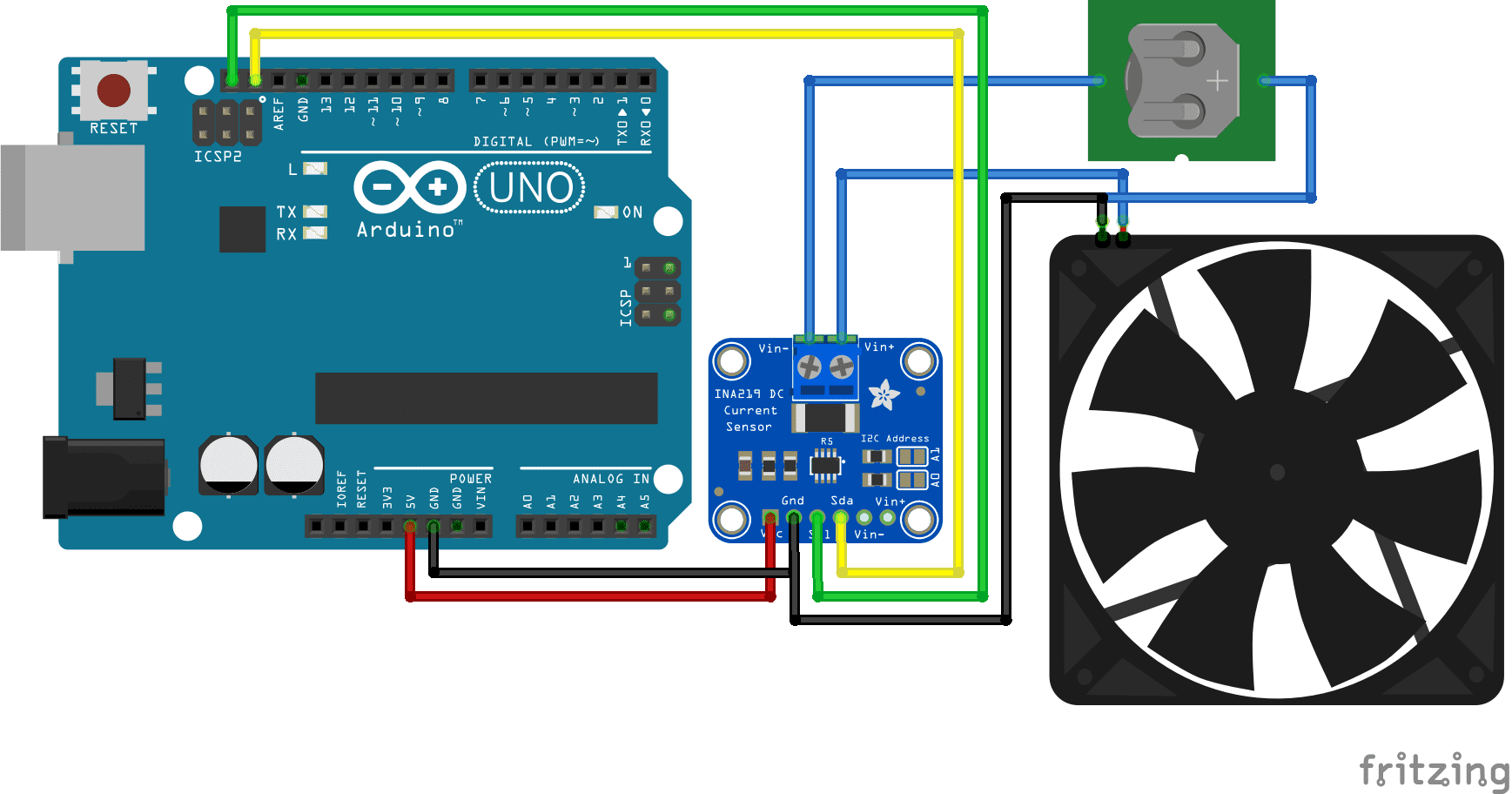
INA219 12bits,IIC interface, 26V, 3.2A with 100mOhm
INA226 16bits, IIC interface, 36V, with exist lib https://github.com/izzarzn/QuantumVoltcurrent shunt has a 2.5uV resolution, it makes the Shunt voltage input range at 81.92mV(2.5 uV * 32768)
so for 100m Ohm, the max current: 81.92mV/100m Ohm=0.8192A
10m Ohm makes 8.192A
5m Ohms 16.4A
10m Ohm makes 8.192A
5m Ohms 16.4A
4m Ohms 20.48A
2m Ohms 40.96A
1m Ohm 81.92A
2m Ohms 40.96A
1m Ohm 81.92A
It seems to me starting with INA219 is right choice.
Adafruit has a INA219 lib with OLED and pixel led.
Adafruit has a INA219 lib with OLED and pixel led.
it works right one my combination, just rotate the OLED display.


留言
張貼留言