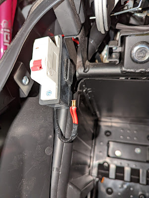
Soco TC 02 collecting information of system
source:
position of connector:
tested guess on the pins of connector
 |
| bus RS485. à 4800 bauds |
the analysis:
 |
| La plus petite période étant de 208 us, la vitesse du bus est : 1/208*1000000 = 4808 , soit : 4800 bauds |
From another post of error code list:
in error 94: communication fail on battery RS485
wire coded with color: Green-red=485+ Green-black=485-I guess it's a Mbus protocol, since there are BMS, motor controller, and soco's controller on the wires.
info on the bus:
CPX BMS using 250kbps can bus message type:
Controller side:
about the battery box:
connection in side battery:
the battery set does have a XT60 connector with 10AWG wire. But the connection to the round connector use a smaller wire.
on the net, lot of reports of melting round connector with modification of motor controller or BMS.
From the BMS, there are 3 wires for communication, all 3 are connector to the connector on top of the battery,but only 2 are connected through the cable from bike.
Black goes to green-red on the connector side =485 A
Blue goes to green-black on the connector side =485 B
Purple goes to Brown-white on the connector side = ?
the right one should be 485 controller.
On the bike, the battery connector, is on the right side, and the wire goes around to the breaker at left side, after the breaker, I think one wire goes to 12V converter and one goes to motor controller.
I don't think the wire connector and the wire size are well designed for handling 30A.the wire is very small AWG, and goes through a long passage, all these will increase the resistance.
https://www.mysupersoco.fr/forums/super-soco-tc-forum/general/sujet/travaux-sur-calculateur-configuration-remplacement/
On the label, it's a 60V, 40A with low voltage protection at 52V, throttle voltage 10.-3.6V
This controller does not regenerate power when breaking or lower down speed. But I think it does handle about 2Kw, 60*40=2400W
the motor continuous output is about 2000W...
But we don't real know what is the exact voltage and amp at 2000W.
abother test on canary island:
On the web of soco TW, it marks the 17" BOSCH
max power:3550W(my registration paper shows 5.02hp~3.7kW)
standard RPM 540RPM
rated torque:25NM
top speed 80Km/h
Since the motor can handle more than the other parts of circuit.
the easiest way is to improve:
1. the wires.
2. the BMS current limit.( we can jump the bat - before the cut off mosfet, but we don't know what is the limit of non-marking battery)
3. increase battery capability, i.e. increase max current, and lower the voltage drop.
4. Replace controller with a regen one, with larger current capability.
If we keep the motor, the arrangement of above items should aim for 3000-4000W continuous power. which could be 70-53V, 50-60A.
This is a fund on internet, it seems lingBo's controller could reach 88V max
https://supersocoforum.com/forum/main/super-soco-tc-motor-info/paged/4/#post-846
above are few try to increase the power, some looks for increasing voltage, some are looking for higher current, since for torque on hill climbing, you will need more current.
Up to now, I saw no one is able to hack the original controller, so there is no chance to work on the sw limitation on current. One through is to cheat on shunt resistor.
the link are some tc and has down load link of Limbo SW, some controller has tx,rx, on the board, then 9600,8,n,1 worked out for him.
================================================
some one modified a linbo controller:
https://cyclurba.fr/velo/898/debridage-scooter-moto-vae-controleur-ling-bo.html
https://www.youtube.com/watch?v=6o7etoezsKY&ab_channel=KPAdventure
In the discussion of above video, it says the max voltage of stock controller is 75V.
any thing above, the stock controller will go into overvoltage protection


留言
張貼留言