#001 ESP32 UART0,1,2 with arduino IDE
I am following Mr. accent swiss' utube for ESP32 learning.
I have update the ESP8266 support to 2.4 and the ESP32 support with latest json file as he mentioned in the film:
I'm interested in multi-UART usage, I learned that there are 3 uarts on ESP32, one is used by USB for debugging, and Serial2 should be on IO16(RX) and IO17(TX), Serial1 is using IO12/IO13, according to his #152 video, IO12 is used internally for flash stuff, so if you try to use :
HardwareSerial2(2) the the processor will crash.
HardwareSerial Serial1(1);
HardwareSerial Serial2(2);
void setup() {
// put your setup code here, to run once:
Serial.begin(115200);
Serial1.begin(115200);
Serial2.begin(115200);
}
void loop() {
Serial.println("This message sent to USB serial");
Serial1.println("This message sent to UART1 serial1");
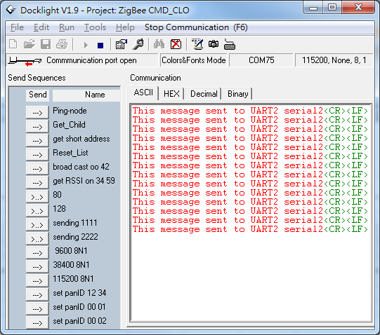
Serial2.println("This message sent to UART2 serial2");
delay(1000);
}
I down loaded to my wemos OLED ESP32, and it did not crash...
According to the pin out I got from http://www.instructables.com/id/ESP32-With-Integrated-OLED-WEMOSLolin-Getting-Star/
the RX/TX marked on my board is actually Rx0/Tx0 which is the same as USB one.

which is consist with what I got on arduino monitor and the docklight with FTDI connected to RX/TX pins on board.


This surprised me, since the video is dated 2017 Oct, and it's corrected. I think there must be some change on the pin define, since ESP32 has very good pin muxing capability. according to the video, this is done with
\hardware\espressif\esp32\cores\esp32\HardwareSerial.cpp
So I find and open it and find in hardware serial.begin
void HardwareSerial::begin(unsigned long baud, uint32_t config, int8_t rxPin, int8_t txPin, bool invert)
{
if(0 > _uart_nr || _uart_nr > 2) {
log_e("Serial number is invalid, please use 0, 1 or 2");
return;
}
if(_uart) {
end();
}
if(_uart_nr == 0 && rxPin < 0 && txPin < 0) {
rxPin = 3;
txPin = 1;
}
if(_uart_nr == 1 && rxPin < 0 && txPin < 0) {
rxPin = 9;
txPin = 10;
}
if(_uart_nr == 2 && rxPin < 0 && txPin < 0) {
rxPin = 16;
txPin = 17;
}
_uart = uartBegin(_uart_nr, baud, config, rxPin, txPin, 256, invert);
}
But I have no intention to change the pin define in the lib. in the messaging of the video, there is one example:
HardwareSerial Serial1(1);
HardwareSerial Serial2(2);
#define TX1_pin 12
#define RX1_pin 13
#define TX2_pin 2
#define RX2_pin 4
void setup() {
Serial.begin(115200);
Serial1.begin(115200, SERIAL_8N1, RX1_pin, TX1_pin);
Serial2.begin(115200, SERIAL_8N1, RX2_pin, TX2_pin);
}
void loop() {
Serial.println("This message is sent to USB Seriall");
Serial1.println("This message is sent to UART1 Serial");
Serial2.println("This message is sent to UART2 Serial");
delay(1000);
}
According to the pinout of my little wemos OLED, I make it as:
HardwareSerial Serial1(1);
HardwareSerial Serial2(2);
#define TX1_pin 15
#define RX1_pin 16
#define TX2_pin 2
#define RX2_pin 4
void setup() {
// put your setup code here, to run once:
Serial.begin(115200);
Serial1.begin(115200, SERIAL_8N1, RX1_pin, TX1_pin);
Serial2.begin(115200, SERIAL_8N1, RX2_pin, TX2_pin);
And it finally works....


I did not understand why the original one did not crash, as saying that io9 and io10 is used for flash...
Here is another very good program for using3 uarts mapping to 3 UDP port.
So, currently I wish to use following pin muxing:
on uart 1
//#define RX1_pin 2// with this config RX=2, TX=4, I can't load the code with FTDI connected
//#define TX1_pin 4
#define RX1_pin 4// with this config Rx=4, Tx=2, I can load the code with FTDI connected
#define TX1_pin 2
HardwareSerial Serial2(2);
#define RX2_pin 14
#define TX2_pin 16
I think that's some thing about how ESP32 access it's flash when boot up....


留言
張貼留言