發表文章

目前顯示的是 2023的文章

Soco TC 05 RS485 decode finding baud rate and contains

圖片
 I knew from web info that it's RS485 connection between units on TC, but the baud rate and format was not found on web. Base on the information I found at least BMS, motor controller, ECU and dash board are connected on 485. I have this 485 module on hand, decide to find out the traffic on 485. I first connect it to a FTDI, with DE/RD both tied to GND to receive data from bus. with ternimal on PC, I start to test on different baud rate, only at 4800 and 9600 I can receive "seems resonable" hex data. These are in 485,  This is 4800bps I tried to group them... 48 EB 01 20 F2 ED 6F 3F 3F 03 00 00 01 20 60 F2 3F 3F 48 3F E3 20 49 ED 6F 23 62 00 00 01 40 F2 3F 3F  48 EB 01 20 F2 ED 6F 3F 3F 03 00 00 01 20 60 F2 3F 3F 12 87 90 3F 3B ED 6F 23 62 00 00 01 40 F2 3F 3F  48 EB 01 20 F2 ED 6F 3F 3F 03 00 00 01 20 60 F2 3F 3F 48 3F E3 20 49 ED 6F 23 62 00 00 01 40 F2 3F 3F  48 EB 01 20 F2 ED 6F 3F 3F 03 00 00 01 20 60 F2  These are in 9600, also try to group it... C5 5...

Soco TC 02 collecting information of system

圖片
  source: https://www.mysupersoco.fr/forums/forum-general/questions-generales/sujet/tracking-complet-de-la-super-soco/ position of connector: tested guess on the pins of connector bus RS485 . à  4800 bauds the analysis: La plus petite période étant de 208 us,  la vitesse du bus est : 1/208*1000000 = 4808 , soit :  4800 bauds From another post of error code list: https://www.mysupersoco.fr/forums/forum-general/questions-generales/sujet/la-bible-des-codes-derreur-et-de-depannage-super-soco/ in error 94: communication fail on battery RS485 wire coded with color: Green-red=485+  Green-black=485- I guess it's a Mbus protocol, since there are BMS, motor controller, and soco's controller on the wires. info on the bus: https://wiki.voltgaraz.cz/index.php/RS-485 CPX BMS using 250kbps can bus message type:  https://wiki.voltgaraz.cz/index.php/CAN Controller side: https://www.mysupersoco.fr/forums/super-soco-tc-forum/general/sujet/travaux-sur-calculateur-configuration...

Servo tester with watt meter(voltage and current) + display Part1

圖片
 function required:  Manual mode(VR or rotary encoder), Centering mode, sweep mode(low limit(800-1400ms)and high limit(1600-2200) settable, sweep speed adjustable) servo supplier voltage adjustable(5-7.2 or 8.4V?) or (by pass and lower to 5V) Current(5~8A should be good) and voltage monitor. Display. current position, voltage, current digital put put for chart plotting(Arduino IDE?) Option: servo signal Frequency setting 50Hz? First select the current sensor and voltage module. I have plenty on hand, basically divided into 2 category: analog current sensor(voltage to be calculated with voltage divider)   such as AS712, Max471, But you will need a MCU with good ADC, I plan to use esp32 for better display effect, but esp32 has bad ADC. Also if you switch between 5V and 3V MCU, the voltage divider need to be different. digital ones. Which has integrated good ADC and voltage divider, and usually has power meter function. and can be powered with 3.3 or 5V. The down side ...

OPenLRS configurator not supported by chrome

From 2022, chrome killed all app on chrome, then this old but good system lost ways of configurate. here is a stand alone version on win32(works at 64 as well)  https://github.com/raul-ortega/openLRSng-configurator/releases/tag/3.8.8 I found this from a search : https://github.com/openLRSng/openLRSng-configurator/issues/35

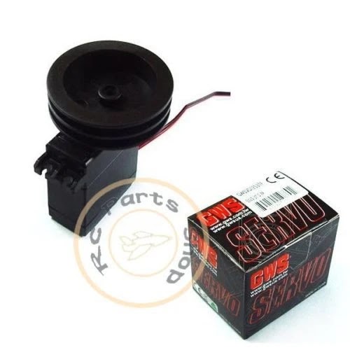
Modify a normal servo to wench servo on RC sail boat.Part1

圖片
 A RC wench servo required several turns, since GWS died, it's not easy to get one. Thunder tiger also have such servo before, but not any more. My first idea is to use step motor, with limit switch on belt(served to get first ), like the rail system in 3D printer. These  ULN2003 + 28BYJ-48 5V  is  very cheap, but after testing, the torque does not seems promising.  The motor is geared, so the holding torque is quite good, but the motor current is quite low, so the turning torque is low, and can be stopped by hand. with SW control with 2 phases engage, is still the same. The multi turn servo has a set of reduction gear on the VR, I came across on web with these toy gear, with 0.5M, I decided to make a reduction gear from out side. I took a metal gear servo, the gear to attached servo horn has a internal M3 threat, I put a very long M3 screw from inside, the the first 15T toy gear is fixed on it. 2nd gear is a 50-10 gear, the the last one(50T) is attached on VR. ...

esp32/8266 as station and TCP or UDP server for multiple connections

圖片
 I have been working on esp32 for serial to udp or tcp server, the idea was to get serial data like GPS or NMEA to be shared over local net work. I did this before, and found out that if your run softAP and TCP server on same core, it could "core 0 panic" I separated then into 2 core, but still failed when 2-3 connected after a while of working. from this post , it seems 8266 is more stable than esp32 on wifi handling?! As broadcasting data, a UDP is more suitable than TCP, Bidirectional communication is not available for the UDP/broadcast protocol. this seems to be a good start:  1 Wifi communication between ESP8266 and PC using TCP/IP or UDP/broadcast protocol I tested it with apmode and udp, but it shows ip unset if I do it in station mode, it does not show "connected to wifi" This one is 3 TCP to serial ports on esp32 2  https://github.com/AlphaLima/ESP32-Serial-Bridge 3  https://github.com/yuri-rage/ESP-Serial-Bridge This fork allow UDP and 8266, but it sa...

Frsky D port decode

圖片
 https://github.com/gke/FrSkyDJTTelemetry work with an OLED, but using serial port of pro mini, so you need a invertor on the serial. it seems mcu can't keep if we use interrupt to make invert signal as next example. I get a 3.3V non-inverted signal from DJT module(it use a 3232EE chip to convert the signal, I found the datasheet and get the original TX signal from MCU.) I get a pro mini 3.3V 8Mhz, hook up with IIC OLED, down load the code, and put the tx from DJT at serial RX, it works fine.   #define NO_INVERTER // uncomment for direct connection of DJT using ~100K resistor   Here is a project to decode D port: using pro mini ,  Decoder for "D" receiver telemetry emitted typically from an early FrSky DJT Tx Module. Code is intended for an Arduino uno or similar. DJT modules uses +/-6V signaling and so an   inverter is required. or using softserial to do the invert job, but need a 100K resistor https://ceptimus.co.uk/index.php/2017/04/21/decoding-frsky-telemetr...

comver Mavlink to passthrough

圖片
 This can do translation from mavlink to passthru https://github.com/zs6buj/MavlinkToPassthru/wiki it works in 3 modes, as I understand it's useful: 1. if your FC does not support s.port ot passthru 2. you can get mavlink through external telemetry, and want to feed into your radio. 3. relay mode, some how complicated for me as a setup. The passthru is at 57600bps, and quite efficient as it use bit map: For telemetry, there were esp dronebridge  using wifi, and this one using espNow for better range:  https://discuss.ardupilot.org/t/simple-esp-telemetry-serial-bridges/75536/32?page=2 https://github.com/yuri-rage/ESP-Now-Serial-Bridge also this one: https://discuss.ardupilot.org/t/espnow-telemetry-rc/90672 https://github.com/Vabe7/ESPnow-Telemetry-RC combine mav2passthu and espnow as tx module.