RC ESC modification part2: schematic and wiring on 1201 gatedrive of RC ESC
How these are connected?
I get the pin out of ATmega 8, and S2101, then using multi-meter to find the connection between S2101 and MCU, as well as back EMF pins. BEMF pins is passing a voltage dividing resistor, very similar to this diagram I found, but the pin connection is very different.

Pin out of S2101

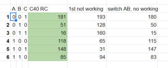
Testing connection between ATmega 8 and 3pcsS2101 gatedrives, (the HIN and LIN to MCU)


Result:
The BEMF reading in pins are the same for 2 sensorless ESC.
result and action:
1. Gatedrives are not driven by PWM pins(although there are 6PWM pins on atmega8), I guess these are using 6 steps square wave to drive 2101.

2. The Serial pins PD0/1 are used, so no need to get a bootloader to control the board under arduino.
3. Next plan to take a arduino board(Ipromini 5V 16Mhz) to connect to the board.I desolded the MCU, was planning to sold jump wires from the MCU pad, but seems the S2101 has larger footprint, should be easier to jump wire, but some location are more tricky.

I got the 3 pairs pwm jumped, also GND and 5V. did not wired the BEMF, because I found that simple FOC does not use BEMF.(sure, I don't think any one will use BEMF for FOC control)


留言
張貼留言