發表文章

Frsky D4R-II 8 channels receiver with telemetry part 2: Lua

I wish to make a lua script for my Jumper T18, with D port data from pixhawk.(pixhawk 1M with D4R reciever). There are old lua script for D port data on taranis radio, I also found a flysky lua script on T16. May be with conbination of these 2 I can get a lua script of Dport on T18  Documentation of openTX inav script is quite complicated, I found the one for tanaris, which only support D receiver and S receiver, is more easier to study: https://github.com/iNavFlight/LuaPilot_Taranis_Telemetry from here :  https://github.com/iNavFlight/LuaPilot_Taranis_Telemetry/blob/master/SCRIPTS/TELEMETRY/LuaPil.lua you can see the data collected, others are based on calculation: Tmp1 is for flight mode, Tmp2 is for GPS fix info, seems to be the same as S.port. -- data.battsumid = getTelemetryId("VFAS") data. vfasid = getTelemetryId ( " VFAS " ) data. celsid = getTelemetryId ( " Cels " ) data. altid = getTelemetryId ( " Alt ...

3DR pixhawk mini with 2MB flash

圖片
 While testing ELRS with pixhawk  I found out that it will as for 2MB flash version of chip to run the ELRS protocol on pixhawk. I have 2 pixhawks on hand(both are 1M version), and 2 3dr pixhawk mini on hand. When I open one pixhawk mini, it marked V3 chip, which is 2MB...BUT... 3DR is long gone, but since this board is designed to target PX4, so some manual data remain . it's a 2MB flash version, but the hardware layout is limited. interfaces: 1 x UART Serial Port (for GPS) Spektrum DSM/DSM2/DSM-X® Satellite Compatible RC input Futaba S BUS® Compatible RC input PPM Sum Signal RC Input I2C (for digital sensors) CAN (for digital motor control with compatible controllers) ADC (for analog sensors) Micro USB Port There is a possibility to use telemetry port (serial1) to work with ELRS RX, then you have no more serial port for planning flight through telemetry. This board support 3 receiver input, which are: CPPM(RCIN port) S.BUS and DMX. S.BUS goes to RCIN port. Not sure where is ...

Frsky D4R-II 8 channels receiver with telemetry part1: data search

圖片
 This is an old receiver, you can still find the spec on web: https://www.frsky-rc.com/product/d4r-ii/ Compatible with FrSky two way telemetry modules: DFT, DJT, DHT, DHT-U manual:  https://www.frsky-rc.com/wp-content/uploads/2017/07/Manual/D4R-II.pdf If you jump CH3/4 signal pins with a jumper, it out put CPPM on ch1 and RSSI on CH2 push the button and power up, it will goes into bind mode, The I turn on my T18, select: protocol Frsky D8 and press bind, it binds ok! I have a invert cable for the telemetry port, this receiver  is the one in iris with a pixhawk(FMUV2, which px4 refer to Pixhawk 1). But now a day, there is not much information on this receiver. I remember read about a D port but now what have is this page: https://docs.px4.io/main/en/peripherals/frsky_telemetry.html Also ardupilot has some info, descript the data contain by D and S port protocol https://ardupilot.org/plane/docs/common-frsky-protocol-info.html The serial mapping is confusing: https://docs.px...

ELRS on Pixhawk 2.4 with ardupilot

圖片
I still have few old FC:3DR pixhawk   I have try to connect my ELRS 2.4G rx to it. since you got RC control and telemetry on one little receiver. But ELRS is relatively recent, not much resource on it. There are also different version of clone. but when flashing with mission planner, it says this is FMUv2 I have set up and bind tested my ELRS  https://ldsrc.blogspot.com/2023/05/crsf-lers-decode-with-arduino-leonardo.html I know it works on RC channel output. First thing is to know the Serial port Nr in mission planner mapping to the labels on my pixhawk. Lucky the mapping is quite straight forward. Pixhawk FMUv2 / Cube FMU v3 Serial Mapping The I follow this instruction: to set serial protocol at 23, and othe https://www.expresslrs.org/quick-start/ardupilot-setup/ My ELRS is at V.3.2.1, we can set the baudrate, since we set 115 in pixhawk, I also set the same in ELRS RX. then it's the chaos...I tried different ports, different baudrate, invert TX/RX(which is not necessary on b...

CRSF ELRS decode with arduino leonardo

圖片
I purchased these from Taobao, about 800NTD for tx, 205NTD as rx... But I'm not sure what is the target I should used with elrs configurator. Seller provide bin as upgrade.  I was playing around, set my binding phase, and get bind, with lua on my jumper T18, it shows connected. I tried to put it on pixhawk 2.4, on telem2, serial 4, set baud rate with my setting on ELRS RX, protocol set to 23, RSSI to 3, even wth RCoption bit 9, but nothing worked.  Since I don't have other flight controller, I decided to find a test on arduino. There are several ones, since my ELRS is 3.0 , I can modify the baud rate. This one works, I have a seeeduino lite with 32U4 and there is a switch for 5V 3.3V pins, I tested it, it works at 115200 baudrate. I can see the read out of the channel data. But, If I modify the baudrate to 57600 on both side, it does not work...not sure why  https://github.com/kkbin505/Simple_RX

RC nitro engine glow plug driver

圖片
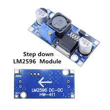
 I used to use a DC DC step down converter to heat up a glow plug, at 1.2-1.4V. I add a switch to control it. It was working, since then, I can use what ever battery I have on hand. It takes 2.26A at 1.2V I did a test, a plug will need about 2A. So, I switch to this kind of DCDC to save volume on car. It does light up the plug on testing, but once on car, it would only start the engine for first few times. After several try, I believe that when glowing a plug on engine, when the fuel goes in to cylinder, it would also take out heat, then I need more current to keep the plug glow. if I power it at 1.4V, it will be 2.8A, when you blow on the glow, it goes up to 4A googling around, I cross to find out that a RC glow plug is about 5W, and there are some on board glower is only using a mosfet to switch power source, An example of arduino for 9 glow: http://philsradial.blogspot.com/2013/02/glowplug-driver.html I wish to power glow drive and the starter motor with same 2s life battery, so...

getting PPM signal from old old 27Mhz radio controller

圖片
 I have an old sanwa car controller, it old but in good Sharpe. I want to convert it to modern 2.4G or LRS, since old AM/FM could be triky these days, when all your analog parts are 20years old. There is only one main chip on PCB, it's OKI  L9362... you can still find the scanned version of datasheet... it takes 4 VR cahnnels into PPM out put... supply voltage range is 6-13V... It has a internal regulator, so the out put is 3.8V... Referencing to data sheet, I power the board with 10V, and take the out put signal with scope. I do get 2 channels. first slot is steeling Here is the back side of th IC, the red V is Vcc, the blue V is Vref(3.8V, where VR is connected to).  The you have channel 1 and channel2, the channel 3 and 4 are bounded, but not grounded. Today, with arduino, it's quite easy to read out the PPM with this library: https://github.com/dimag0g/PPM-reader it use interrupt so, no delay on your system, and can pretty mature. now, the question is: what RF  t...